Understanding the Working Principle of a Digital Multimeter
A digital multimeter (DMM) is an essential tool in the field of electronics and electrical engineering. It is used to measure various electrical parameters such as voltage, current, and resistance. Unlike analog multimeters, which use a moving needle and a printed scale, digital multimeters display measurements in numeric form on an LCD or LED screen. This article delves into the working principle of digital multimeters, explaining their components, operation, and the technology behind their accurate measurements.

Components of a Digital Multimeter
A digital multimeter consists of several key components that work together to measure electrical parameters accurately. These components include:
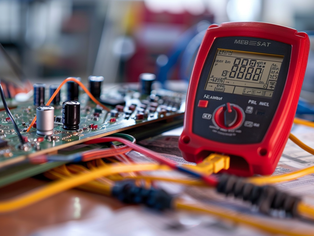
- Display: The display is typically an LCD or LED screen that shows the measurement results in numeric form.
- Selector Switch: This switch allows the user to select the type of measurement (voltage, current, resistance) and the range of the measurement.
- Input Jacks: These are the terminals where the test leads are connected. Common jacks include the COM (common), VΩ (voltage and resistance), and A (current) jacks.
- Microcontroller: The microcontroller processes the input signals and converts them into digital values that can be displayed on the screen.
- Analog-to-Digital Converter (ADC): The ADC converts the analog signals from the input into digital signals that the microcontroller can process.
- Power Supply: Digital multimeters are usually powered by batteries, which provide the necessary energy for the device to operate.
Working Principle of a Digital Multimeter
The working principle of a digital multimeter involves several steps, from input signal acquisition to the display of the measurement results. Here is a detailed explanation of the process:
1. Signal Acquisition
When measuring a parameter, the user connects the test leads to the input jacks and places the probes on the points to be measured. The selector switch is set to the appropriate measurement type and range. The input signal (voltage, current, or resistance) is then acquired through the test leads.
2. Signal Conditioning
The acquired signal is often not suitable for direct conversion to a digital format. Therefore, it undergoes signal conditioning, which may include amplification, attenuation, and filtering. For example, if the input signal is too weak, it is amplified to a level that the ADC can handle. Conversely, if the signal is too strong, it is attenuated.
3. Analog-to-Digital Conversion
Once the signal is conditioned, it is fed into the ADC. The ADC converts the analog signal into a digital signal by sampling the input at regular intervals and quantizing the signal into discrete values. The resolution of the ADC (e.g., 8-bit, 10-bit, 12-bit) determines the accuracy and precision of the conversion.
4. Digital Processing
The digital signal from the ADC is then processed by the microcontroller. The microcontroller performs various calculations and corrections to ensure the accuracy of the measurement. For instance, it may apply calibration factors, compensate for temperature variations, and filter out noise.
5. Display of Results
After processing, the microcontroller sends the final measurement value to the display. The result is shown in numeric form on the LCD or LED screen, making it easy for the user to read and interpret the measurement.
Measurement Modes
Digital multimeters can measure various electrical parameters, each requiring a different measurement mode. Here are the common measurement modes and their principles:
Voltage Measurement
When measuring voltage, the multimeter is connected in parallel with the component or circuit under test. The input voltage is divided down to a level suitable for the ADC using a voltage divider network. The ADC then converts the scaled-down voltage to a digital value, which is processed and displayed by the microcontroller.
Current Measurement
For current measurement, the multimeter is connected in series with the circuit. The current flows through a precision shunt resistor, creating a voltage drop proportional to the current. This voltage drop is measured and converted to a digital value by the ADC. The microcontroller then calculates the current using Ohm’s law (I = V/R) and displays the result.
Resistance Measurement
In resistance measurement mode, the multimeter applies a known voltage to the resistor under test and measures the resulting current. Using Ohm’s law (R = V/I), the microcontroller calculates the resistance value. The ADC converts the voltage and current measurements to digital values, which are processed and displayed by the microcontroller.
Advanced Features
Modern digital multimeters come with advanced features that enhance their functionality and usability. Some of these features include:
- Auto-ranging: The multimeter automatically selects the appropriate measurement range, eliminating the need for manual range selection.
- Data Hold: This feature allows the user to freeze the displayed measurement value, making it easier to read and record.
- Min/Max Recording: The multimeter records the minimum and maximum values during a measurement session, providing insights into the variations in the measured parameter.
- Continuity Testing: The multimeter emits an audible beep when it detects a low resistance path, indicating continuity in a circuit.
- Diode Testing: This mode allows the user to test the forward and reverse bias characteristics of diodes, providing information about their health and functionality.
Conclusion
Digital multimeters are versatile and indispensable tools for anyone working with electrical and electronic systems. Their ability to measure voltage, current, and resistance with high accuracy and precision makes them essential for troubleshooting, testing, and development tasks. Understanding the working principle of digital multimeters helps users appreciate the technology behind these devices and use them more effectively in their work.
While this article provides a comprehensive overview of the working principle of digital multimeters, it is always recommended to refer to the user manual of a specific model for detailed instructions and safety guidelines. As technology advances, digital multimeters continue to evolve, offering more features and improved performance to meet the growing demands of the industry.

